Designed to meet the unique challenges of electrical distribution in high rises, the revolutionary HighBus is the latest iteration of the Superior Bus.

The latest patented design by STS, the system is intended to go higher up a building than anything else currently on the market.
Cable bus can be used in a wide range of utilities, industrial and municipal projects which require direct connection between a source and load.

UNIQUE BENEFITS
- Cost effective
- Fail proof
- Fully wet/dry rated
- Easy modular installation
- Patented technology
- 2-year full warranty
UNIQUE TECHNOLOGY
Designed to survive extreme water events Solution to 110.14 (C) cable bus connection requirement
The HOLLOBUS system is the next step on the cable bus electrical power distribution “evolutionary” scale. It’s the natural replacement of the cabling and of the non-reliable bus ducts.
Our system is intrinsically safe, flexible, reliable and efficient. It is capable of ampacity and voltage (up to 15kV) customization, based on project’s requirements.
The system provides numerous advantages to the contractor/ customer including substantial cost savings on labor, maintenance and space. Furthermore, our system minimizes power loss and voltage drop.
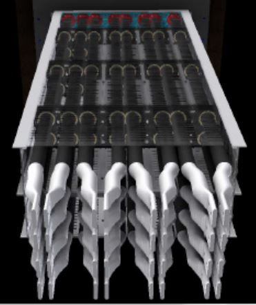
The current carrying materials of the HOLLOBUS system are aluminum and copper, but that’s where the similarity to other power distribution systems ends.
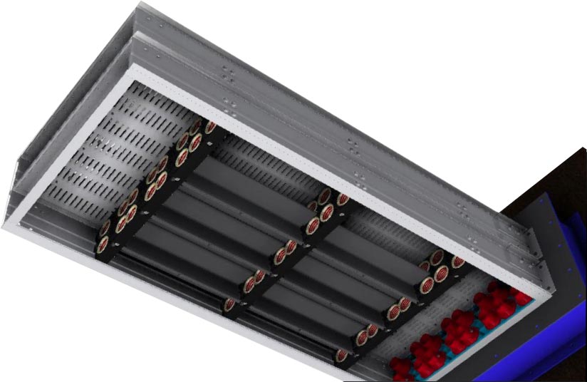
Regular busduct uses adjacent flat bus bars, which results in low thermal efficiency. Our HOLLOBUS system is designed around spaced hollow conductors, which increase thermal efficiency and
reduce electromagnetic interference caused by skin effect and balancing.
Conductors are arranged to cope with the magnetic fields in the system by using a our conductor shielding technology, which minimizes the electromagnetic interference between conductors.
FEA Analaysis – Thermal Image >
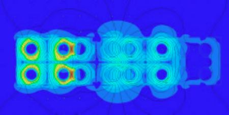
The aluminum enclosure has been carefully designed to reduce the weight of the system and to minimize the hysteresis and eddy current losses that are common in all-steel housings. It also helps to reduce magnetic flux leakage. Bundling the conductors lowers the inductance just like bundles in transmission lines. So, it’s not magic, just an innovation in electromagnetics and good old engineering know-how.
ROBUST DESIGN | NO CHANCE FOR A FAILURE
- Up to 25% less voltage drop than traditional busduct
- Up to 70% more length of the runs than traditional busduct
- More adaptability and versatility (*1” length tolerance per floor)
- Easy installation
- Easily stackable to build bigger systems
- Operationally safe and durable
- Low temperature and naturally passive cooling
- Fully tested (short circuit, heat rise, earth fault, breakage, grip, span)
- Certified to UL, CSA, NOM, Management certification ISO 9001
- Future expansion flexibility
- Higher integrity and reliability (99-years structure lifespan)
- Suitable for DC applications
Ventilated traditional busduct depends on free air movement through a perforated housing to cool the bus bars. Unless mounted in its preferred position (for maximum bus bar cooling), ordinary ventilated busduct must be de-rated. The HOLLOBUS system is designed for the worst case scenario and does NOT need de-rating, regardless of the position.
*assuming proper installation and use
FLEXIBILITY & EASY INSTALLATION – ANYWHERE
In ordinary busducts, busbars cling to each other, thus making them prone to electrical failure. Numerous failures and explosions in busways, due to water, testify to this problem.
Also, ordinary outdoor busducts must remain energized at all times to maintain a constant temperature in order to avoid failure (due to seal breakdown and /or condensation buildup). Thus, increasing their maintenance cost.
By contrast, the HOLLOBUS system is impervious to any water event, whether is energized or not. Our patented sealing technology allows water to pass though the system without any detrimental effects. You will never have to fear rain, snow, floods etc. ever again!
The HOLLOBUS system is adjustable. Our patented technology allows ±1 inch of length tolerance every floor. This is critical especially for contractors, as floor height deviation is a common
phenomenon in high-rise constructions. Furthermore, due to its modular nature, the HOLLOBUS system can be easily lengthened or shortened by adding or removing cassettes (modules).
Unlike busduct in which all phases are connected with a single bolt and is inherently inflexible, the HOLLOBUS system is sway-friendly. The system’s exclusive flexible joints embedded in tap boxes absorb buildings’ natural oscillation, environmental sway, and cyclical expansion and contraction due to load demand changes. Consequently, the HOLLOBUS system is incredibly safe in case of earthquakes!
The HOLLOBUS system is easy to install. Our modular system stacks up all the way to the top of the high-rises, floor by floor, with reduced workforce, thus generating substantial savings in labor cost. The HOLLOBUS system cassettes can be paralleled together making our system unique in terms of ampacity. As such, even big systems up to 8000A can be done with Aluminum.
UNPRECEDENTED DURABILITY
Insulation plays the leading role in electrical distribution systems. In the HOLLOBUS system, we use a durable, long-life, chemical/ water resistant epoxy insulation. This self-extinguishing epoxy is UL certified in accordance with UL746B. The standard consists of various tests of humidity, cold shock, vibration, heat and etc .
The coating receives a Relative Thermal Index (RTI) of 130°C, which is the highest an epoxy insulating coating powder has achieved to date. Essentially, it means it can last 100,000 hours at 130°C before half of its properties deteriorate. This high tech insulation enables the HOLLOBUS system to operate at high ambient temperature of 50°C to a maximum of 105°C operating temperature.
Equally important, our environmental seals are designed to prevent fire & water penetration from floor to floor. These patented water seals and fire stops add another layer of safety and reliability to our HOLLOBUS system. Our floor seal system is designed to carry the localized load of that floor, therefore eliminating the need for special spring hangers and loading brackets. This generates cost savings for simplified installation.
Fully tin-plated connections help reduce resistance at joints. In addition, Belleville washer eliminates labor-intensive re-torqueing and is a great help by simplifying your maintenance program.
TESTED & CERTIFIED FOR YOUR PEACE OF MIND
All systems manufactured by SUPERIOR TRAY SYSTEMS are fully certified to CSA and UL standards.
Our all-aluminum enclosure provides a low impedance ground path for ground fault current. The ground resistance, inherent to the HOLLOBUS system enclosure, conforms to NEC 250-94 standard for minimum ground conductors. To increase the safety, we have added two internal ground conductors, integrated in the system.
The HOLLOBUS system is patented and exclusive to SUPERIOR TRAY SYSTEMS. Designed by our company with UL listed resin and synthetic rubber, EnviroSeal is our patented water insulator which guaranties highest dependability and reliability.
NEMA 3 or 4 rated joining enclosures will eradicate any concerns of water penetration failure into connecting equipment.
EXAMPLES OF MECHANICAL SPECIFICATIONS
The HOLLOBUS system was primarily designed for vertical applications and specifically to minimize the feeder count needed to provide power up the building.
We have multiple feeder configurations in both aluminum and copper conductor designs to meet the buildings needs.
Most buildings can be condensed to a SINGLE feeder when using the HOLLOBUS system, saving you space, time and money.
If using a traditional bus way design, you would need to provide a top and bottom fed tenant feeder, requiring yet another feeder to connect the penthouse substation gear to the incoming feed in the basement. With the HOLLOBUS system, we can power the entire building, from the basement (only at 208V), thus eliminating the need for multiple systems, space and cost of mid or top level substations.
HOLLOBUS VOLT DROP TABLE
MAX. SYS. AVAILABLE LINEAR RUN LENGHT (feet) OF DISRIBUTED LOAD TO REACH 3% VD MAX (V=208, PF=90%)
| MODEL # | MATERIAL | AMPACITY RATING | 8000A | 6000A | 5000A | 4000A | 3500A | 3000A | 2500A | 2000A | 1500A | 1000A |
| HBA08TN-S3 | AL | 1500A | x | x | x | x | x | x | x | x | 206 | 308 |
| HBA08TK-S3 | AL | 1750A | x | x | x | x | x | x | x | x | 290 | 436 |
| HBA16TN-S3 | AL | 3000A | x | x | x | x | x | 208 | 250 | 312 | 416 | 624 |
| HBA16TK-S3 | AL | 3500A | x | x | x | x | 258 | 300 | 360 | 452 | 602 | 902 |
| HBA24TN-S3 | AL | 4400A | x | x | x | 230 | 264 | 308 | 370 | 462 | 616 | 926 |
| HBA32TN-S3 | AL | 5400A | x | x | 242 | 302 | 346 | 404 | 484 | 606 | 808 | 1210 |
| HBA16TN16TK-S3 | AL | 5800A | x | x | 276 | 344 | 394 | 460 | 552 | 690 | 920 | 1378 |
| HBA32TK-S3 | AL | 6300A | x | 290 | 348 | 434 | 496 | 580 | 694 | 868 | 1158 | 1738 |
| HBA48TK-S3 | AL | 9500A | 326 | 434 | 522 | 652 | 744 | 868 | 1042 | 1304 | 1738 | 2606 |
| HBA64TK-S3 | AL | 12500A | 430 | 574 | 688 | 860 | 982 | 1146 | 1376 | 1720 | 2292 | 3440 |
| MODEL # | MATERIAL | AMPACITY RATING | 8000A | 6000A | 5000A | 4000A | 3500A | 3000A | 2500A | 2000A | 1500A | 1000A |
| HBC08TN-S3 | Cu | 1700A | x | x | x | x | x | x | x | x | 278 | 416 |
| HBC08TK-S3 | Cu | 2000A | x | x | x | x | x | x | x | 270 | 358 | 538 |
| HBC16TN-S3 | Cu | 3400A | x | x | x | x | x | 284 | 342 | 426 | 570 | 854 |
| HBC16TK-S3 | Cu | 4000A | x | x | x | 290 | 330 | 386 | 462 | 578 | 772 | 1156 |
| HBA24TN-S3 | Cu | 5000A | x | x | 250 | 312 | 358 | 416 | 500 | 626 | 834 | 1250 |
| HBC32TN-S3 | Cu | 6100A | x | 274 | 330 | 412 | 470 | 550 | 660 | 824 | 1098 | 1648 |
| HBC16TN16TK-S3 | Cu | 6600A | x | 310 | 372 | 464 | 530 | 620 | 744 | 930 | 1240 | 1858 |
| HBC32TK-S3 | Cu | 7200A | x | 370 | 444 | 554 | 634 | 740 | 888 | 1108 | 1480 | 2220 |
| HBC48TK-S3 | Cu | 10800A | 412 | 550 | 660 | 826 | 944 | 1102 | 1322 | 1652 | 2204 | 3306 |
| HBC64TK-S3 | Cu | 14400A | 548 | 730 | 876 | 1096 | 1252 | 1460 | 1752 | 2190 | 2920 | 4380 |
Notes:
- Volt drop calculator is based on voltage of 208V and a distributed load
- For a concentrated load, divide the length by 2
- For a volt drop based on 480V, multiply the length by 2.3
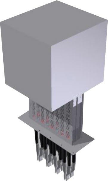
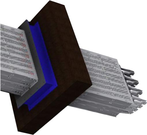
HOLLOBUS GEAR INTERFACE
The HOLLOBUS gear interface is designed to meet the requirements of article 110.14 (C)
The interface allows a superior bus product to connect to the interface at a 90o C free air rating, finally no more derating for your low voltage cable bus applications.
The HOLLOBUS interface connects to the gear connections with a flexible interface on one end and has a 90o C rated cable connection on the other end. These systems are designed to be dropped into place and bolted up with minimal labor.
As always, all SUPERIOR TRAY products will seamlessly connect to each other. SUPERIORBUS, HIGHBUS and HOLLOBUS can all be used on a single feeder if required.
Visit https://hollobus.com/ for more information.