The step-by-step installation guide For Your Cable Bus System
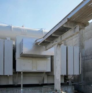
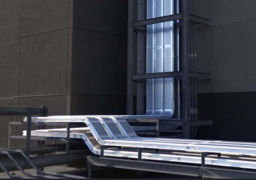
It can be hung from the ceiling, wall mounted both indoors and out, and installed underground in a ventilated trench. We have the experience to help you specify the correct mounting, expansion, and support systems for your particular application.
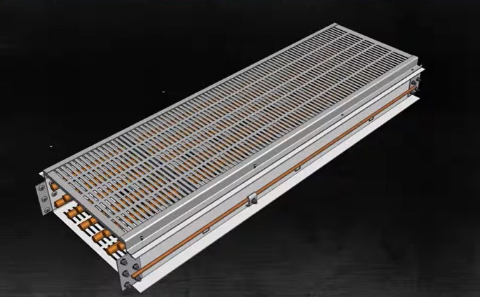
This guide shows the installation of a standard system
Keep in mind that every project is designed on a case-by-case basis. Please refer to your specific drawing package for more details as it explains the particular installation needs such as part numbers, bolted configurations, and accessories for your specific project.
Safety
Our systems have been rigorously tested to comply with UL and CSA standards. In order to achieve the highest level of system safety it is important to thoroughly understand and follow these installation instructions.
These systems should only be serviced by trained professionals. Before any service or installation work is done ensure that the system is safely disconnected from the power source and that any capacitive loads have been discharged. Check the cables with an inductive ammeter before service.
Conduct tests according to the system specifications before re-energizing the system. The ground cable is essential to avoid risk of death and equipment damage. It is highly recommended to drill the ground clamp holes and install the ground cables and bonding clamps prior to pulling the cables to avoid damage to the conductors.
The tools required for this installation are:
- #2 Robertson screwdriver
- 3/8 drive torque wrench
- 7/16 socket
- 9/16 socket
- drill with a 7/16 drill bit
- 5/32 allen key or allen driver bit
- #2 Robertson driver bit
For our cable cut calculations we use a central line length taken from our approved drawings plus the stick out required on both ends for termination.
Assembling the enclosure assembly
Assemble the tray as per the layout drawing that we provide in a customer drawing package. Install the splice plates and splice hardware, leaving the bolts loose enough for adjustment. Ensure the tray is supported as per the Electrical Code. This will vary depending on where the system is being installed. Once the system is fully installed tighten down the splice hardware.
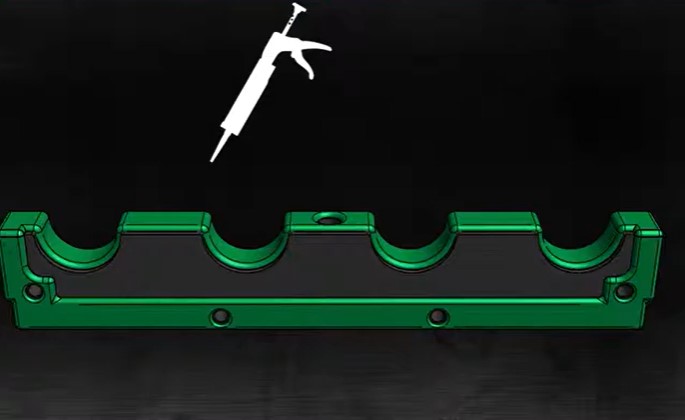
Now we will show you how to install the cable support blocks using a standard bolting configuration. Please note if you have an alternate bolting configuration or machine blocks, please refer to your customer drawing package for installation details.
Steps for a cable bus assembly
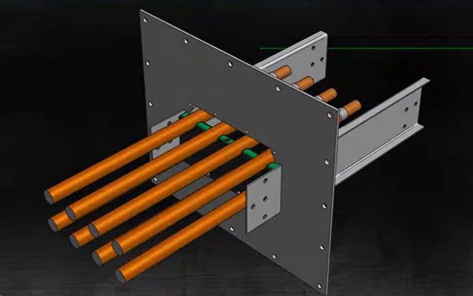
(1) Lay the first row of cables over the bottom support blocks which are pre-installed in the trays.
Installation is made easier by marking each cable by phase using a different color of electrical tape for each phase.
(2) To temporarily hold the middle block in place, loosely install one or two bolts in through the bottom and middle blocks.
(3) Pull the second row of cables over the temporarily installed support blocks.
(4) Remove temporary support block bolts.
For three-tier systems, repeat steps 2, 3, & 4 for the third row of cables.
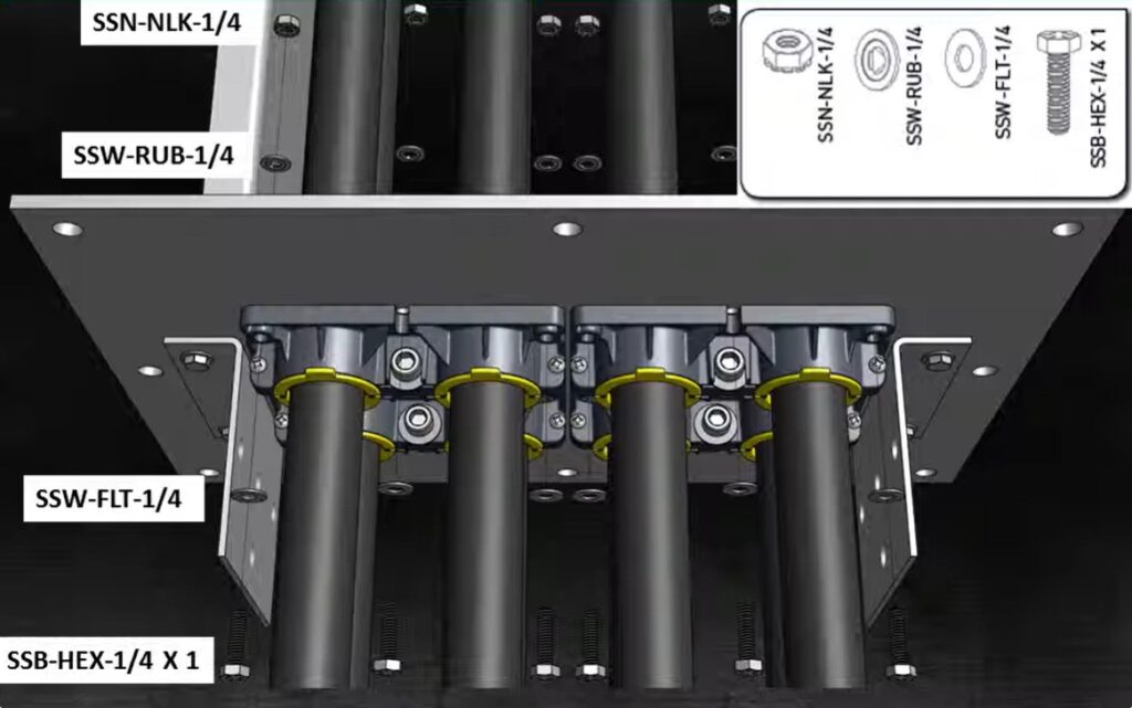
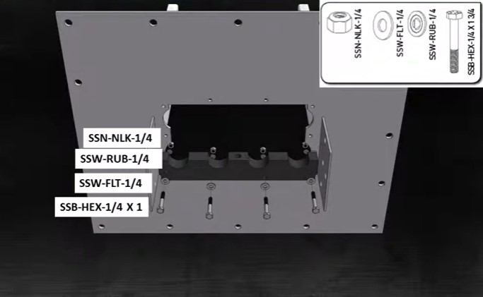
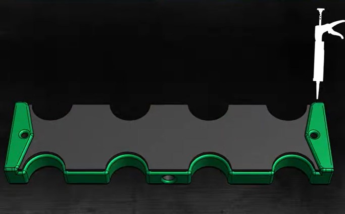
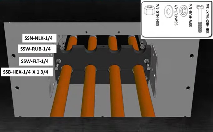
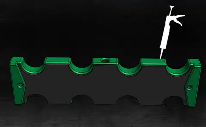
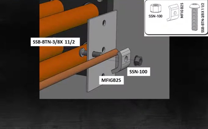
(5) Install top support block secure using the appropriate bolts and washers. The image shown on the screen is used as an example.
Installation of environmental seals
There are two types of seals, a molded seal and a machined seal. Please refer to your customer drawing package for information on which seal you have for your specific system.
Installation of the molded seal
It is important to know that the molded seals have been supplied pre lubed with dielectric silicone grease. Ensure that the guides are kept clean and free of dirt and debris during installation. If the guides become contaminated, wipe the guide with a clean lint-free cloth and reapply dielectric silicone grease.
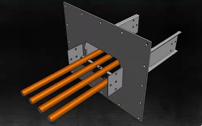
(1) Pull all the cables through the seal plate using caution to avoid damage to the cable insulation. Prepare the cables for termination. Ensure that sealant is used for mounting the plate to the wall or to the equipment during seal plate installation.
Please note that the cable bus enclosure is omitted for clarity in the image shown.
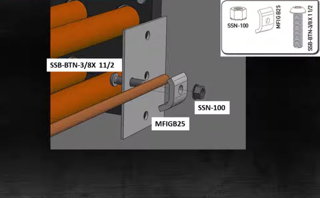
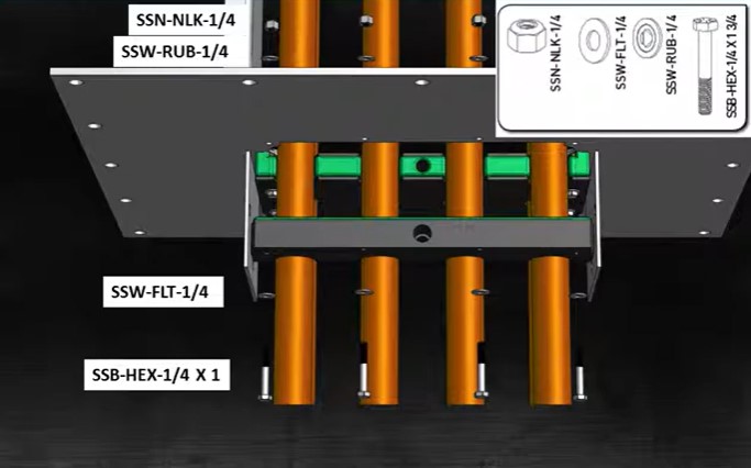
(2) Install the bottom block using the hardware shown. Leave bolts hand tight for now.
(3) Suspend the upper row of cables while securing the lower row. Bolt the middle block to the bottom block using the hardware shown. Torque the bolts to sixty inch pounds or five foot pounds. In the image shown, the second row of cables are not shown for clarity.
(4) Install the side screws hand tight. Do not over tighten the screws or the bottom block may crack.
(5) Bolt the middle block to the plate using the hardware shown. Tighten the bolts finger tight.
(6) For a three-tier system repeat steps 3, 4, & 5.
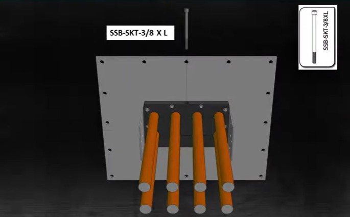
(7) Bolt the top block to the middle block using the hardware shown. Torque the bolt to sixty inch pounds or five foot pounds.
The top block will be painted to distinguish the top block from the bottom block as the top block has had the screw holes enlarged to prevent the top block from cracking.
(8) Install the side screws. Do not over tighten the screws or the middle block may crack.
(9) Bolt the top block to the plate using the hardware shown. Tighten the bolts finger tight.
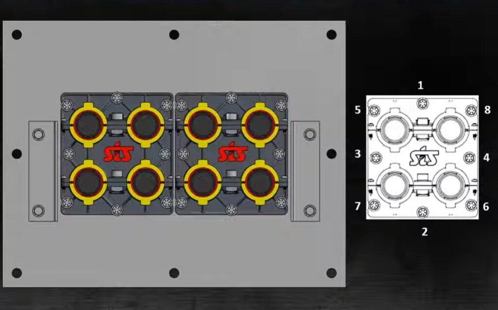
(10) Tighten the blocks to the plate using a crisscross pattern as showing the image. Torque the bolts to sixty inch pounds or five foot-pounds.
(11) Install the ground cable and the clamp.
Installation of a machine seal
The seal blocks are pre-installed onto the seal plate with hardware. Before removing the seal blocks from the plate note how the hardware is installed. During installation ensure that the seal blocks and hardware are installed onto the plate in the same manner as they were shipped.
STS will supply enough caulking tubes of butyl sealant for the installation of the machine seals. If the seal blocks have to be removed for whatever reason during installation and there’s not enough butyl sealant leftover to reapply to the seal blocks, ensure that a quality butyl rubber based gutter and flashing sealant is used. Do not use latex, acrylic, or silicone sealants as they do not provide adequate sealing or lifespan for your SuperiorBus system.
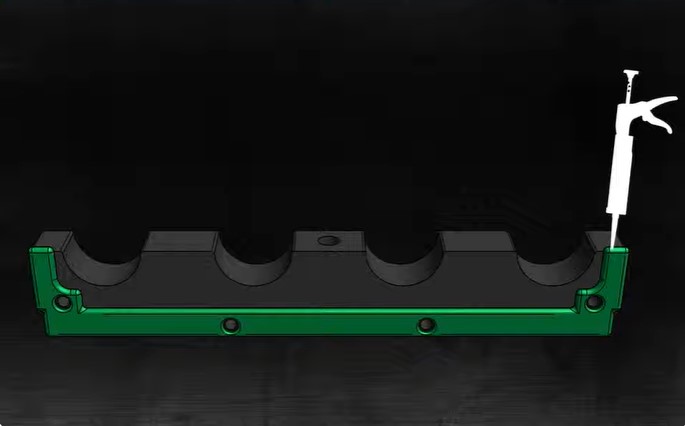
(1) Apply butyl sealant to the seal block as shown in the image.
(2) bolt the bottom block to the plate using the hardware shown in the image.
(3) Pull the cables through the seal plate using caution to avoid damage to the insulation. Prepare the cables for termination.
(4) Apply a sealant around the cable holes as per the image shown and lay the cables into their appropriate spaces.
(5) Apply butyl sealant to the middle block as shown in the image
(6) Suspend the upper row of cables while securing the lower row. Seal the middle block to the seal plate and install the block using the hardware as shown in the image. Please note that the upper cables are hidden for clarity in the image shown.
(7) Apply butyl sealant to the cable holes as for the image shown and lay the cables in their appropriate spaces.
(8) repeat steps 5 6 & 7 for a three-tier system.
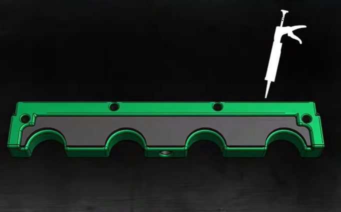
(9) Apply butyl sealant to the top block as per the image shown.
(10) Seal the top block to the plate and cables. Install the seal blocks using the hardware shown.
(11) Install the compression bolt if applicable and let the sealant dry for 24 hours in a dry environment before energizing the system.
(12) Install the ground cable
Installing the ventilated cover cover
Screws are required at maximum interval of 24 inches apart and 2 inches from each end of the cover. Use the self drilling cover screw to secure. Note that the cover is the last step before performing a high pop test and energization.
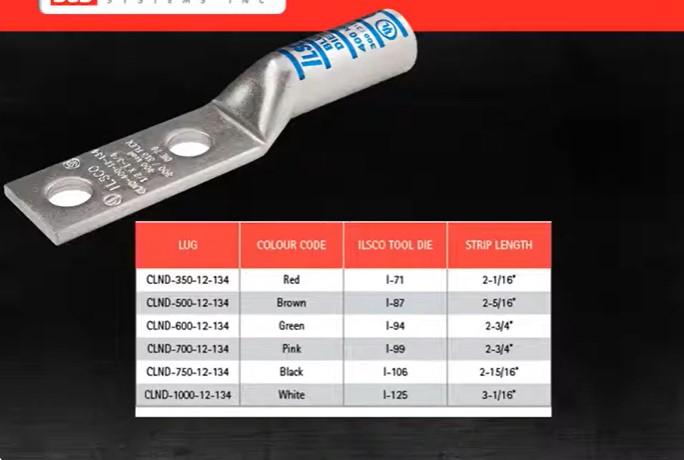
The next part of the installation is the installation of the compression lugs.
(1) Strip the length of insulation according to the dimension defined in a table shown.
(2) Crimp the lugs in the manner specified by L scope for the specific lugs supplied. Crimp connections are UL and CSA certified when the correct crimping tool is used. Crimping tools from (these listed manufacturers) can be used as long as the tool and the lugs have been tested together. For Ilsco brand crimping tools use the dies is defined shown in the table. Refer to Ilsco form 158 for complete definition of the number of crimps and for information on other brand crimping tools.
(3) Clean the parts with solvent if they are dirty. For terminations to copper bus use silicon bronze hardware and tighten the bolts to 40 foot pounds. It is necessary that the correct nut, bolt, and washer combination are used. Refer the Ilsco torque index for installation details.
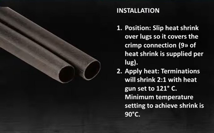
Heat shrink terminations are used in low voltage systems to insulate cable terminations. The heat shrink terminations are UV resistant, fungus resistant, and self extinguishing in event of a fire.
The operating temperature to heat shrink terminations is minus 55 Celsius to 125 degrees Celsius as defined by UL and CSA.
(1) Slip the heat shrink over the lugs so it covers the crimp connection. 9 inches of heat shrink are supplied for each lug.
(2) Apply the heat. Terminations will shrink 2 to 1 when the heat gun is set to 121 degrees Celsius. Minimum temperature to achieve shrink is 90 degrees Celsius.
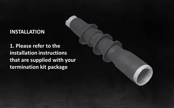
Cold shrink terminations are used on medium voltage systems.
For cold shrink termination installation please refer to the installation instructions that are supplied with your termination kit package.
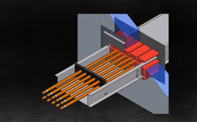
The MCT fire stop allows cables to pass through building walls and floors and will maintain the highest level of fire smoke and water protection. It also protects against cable pullout due to shock and vibration.
Please refer to your customer drawing package for specific installation details.
Fire rated wall seals are designed to provide a two hour fire stop rating in a building wall penetration. They are easily installed by compressing and stacking fire stop pillows into the wall opening.
For fire rated wall seal installation please refer to the spec seal fire stop pillow installation instructions as well as your customer drawing package for more details.
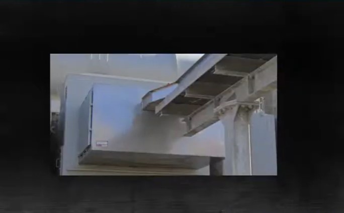
STS can supply enclosures for NEMA 1 to NEMA 4x. For specific installation instructions, please refer to your customer drawing package.
questions about the SuperiorBus step-by-step guide to installation? call 253-579-4473 or contact us now
Related Posts