Before initiating any design, it is important to specify whether you will need an equipment grounding conductor and if the cable bus should be a 3-phase, 3-wire system or a 3-phase, 4-wire system. If an equipment grounding conductor will be needed then it should be supported every 6 to 8 ft as it will be run along the exterior of the housing flange. Other factors to consider include the required basic impulse level, minimum bending radii, and whether full or half neutral is needed.
View Our Modular Cable Bus Power Distribution System Products
Short-Circuit Bracing
Bracing of conductors helps the cable bus system to withstand massive momentary short circuit forces. Check certified test reports that verify the ability of your cable bus system to withstand certain fault current levels. Support blocks are often spaced every 18 inches for vertical runs and 36 inches for horizontal lines. The distance between the conductor support blocks is minimized to obtain higher short-circuit bracing ratings.
Sizing of the Conductor
When sizing conductors, many systems use a “free air rating” due to the amount of ventilation both at the top and bottom of a cable bus enclosure. However, you can take a conservative approach depending on the specific application. According to the National Electrical Code (NEC), the minimum size of the conductor should be 1/0 AWG. Your cable bus manufacturer can perform an actual temperature rise test to verify the correct conductor sizing.
Phasing Arrangements
Unlike bus duct structures, a cable bus system is comprised of a lower voltage drop because the conductors are continuous. Bus duct splices are often bolted together after every 6 to 8 feet, which can create a potential problem if it becomes loose due to thermal cycling. The correct cable arrangement should be calculated during the cable bus design process since the transposing of conductors is rarely needed.
Installation Pointers
You should make an induced shield voltage calculation and a pulling tension for, particularly long or complex cable runs. Cable bus housings come in precut lengths and the bottom segments of the support blocks are often fitted in place. The results of the induced shield voltage calculation determine whether the conductor’s insulation shield should be grounded at both ends. The results from the pulling tension calculation determine whether you will require a splice box.
Environmental Concerns
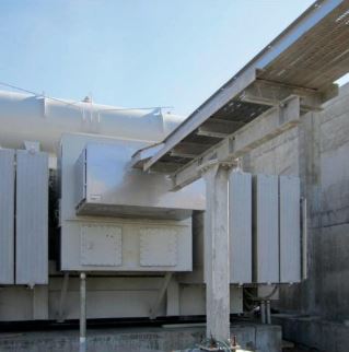
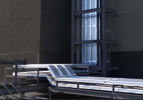
A cable bus system is suitable for both indoor and outdoor use as long as its conductors are fully insulated and well ventilated. Some of the common materials used in a cable bus enclosure include stainless steel, hot-dipped galvanized after fabrication steel, and aluminum. Of all the above options, an aluminum housing works great for most applications when the top and bottom covers are slotted for ventilation and corrugated for additional strength.
Engineered Drawings
As a matter of standard practice, manufacturers often supply installation manuals, layout drawings, and final construction drawings. Some of the details that may be required to assist with the preparation of engineered drawings include elevation views of intended installation, sketches or general layout of the intended installation, and equipment details. Termination boxes may be furnished with transformers and top hats with switchgear to allow the right amount of space for transposing and terminating the cable bus conductors.
Flexibility
Cable bus systems should adapt to the large number of unforeseen indoor and outdoor circumstances that often occur during construction. It is important to be equipped with every size and rating of cable bus including extra cables so that you can adjust the system to accommodate differences between actual field construction and engineering drawings with little or no delay.
The right cable bus system should optimize electrical installation costs while adhering to the regulatory codes and standards. Your system should be capable of withstanding large magnetic forces that may occur during faults while holding conductors reliably in place. The key to a successful operation of the cable bus system is to choose the best cable for the application, conduct a proper installation, and provide regular maintenance for sustainability and longevity.
Interested in a Customized Cable Bus Power Distribution System for Your Project?
Call 253-579-4473 or Contact Us for a Quote.
Additional Resources
Related Posts