Cable Bus Electrical Properties
Explore the unique electrical properties and design considerations of Superior Cable Bus systems from Harbor Energy Solutions. From advanced grounding solutions to impressive short circuit capacity and low-voltage drop, our cable bus systems provide reliable, high-performance power distribution. Learn how we balance system load, utilize parallel conductors, and ensure safety and efficiency for various applications. Discover why our SuperiorBus systems are an ideal choice for robust electrical infrastructure.
SuperiorBus Electrical Distribution Design, Grounding, and Performance
The electrical design principles and values described here are useful in understanding the fundamentals of a Superior Bus system. Please contact one of our experienced technical staff with any additional electrical inquiries.
Grounding
Ground currents tend to concentrate near power conductors and the cable enclosures take a large portion of the ground currents. Should a fault condition occur due to lightning or a failure in an electrical system, the cable bus could be considered to be a carrier of ground currents. To ensure the protection of lives and property caused by these electrical faults, Cable Bus systems are grounded to the substation ground grid and the building steel by means of the support materials.
Additionally, the cable bus system is also grounded to the equipment or the switchgear enclosure by means of a box connector. Grounding of the enclosure will prevent a potential above ground on the enclosure in the event of an electrical fault.
Electrical Properties
| Feature | Specification |
|---|---|
| Material: | 6063-T6 Aluminum |
| Resistance: | 16 µΩ/ft |
| Resistance across splice: | 11 µΩ |
| Resistance of 24 ft length with splice: | 197 µΩ |
| Copper equivalent: | 1250 MCM |
| Continuous current rating (50°C Rise): | 1260 A |
| One second rating (50°C Rise): | 68,500 A |
| Continuous current rating (50°C Rise): | 1260 A |
| Conductivity: | 53% |
| Electrical resistance @ 20°C: | 15.37 µΩ / in2 / ft |
| Electrical resistance @ 20°C: | 19.57 Ω / CM / ft |
System Balance
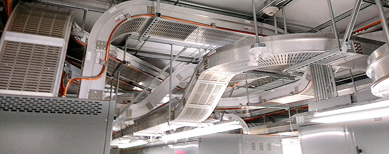
Cable bus is a power distribution system in which current in carried by multiple conductors running in parallel. Insulated power cables are spaced evenly using support blocks. The spacing is designed to achieve free air rating. As such, no current derating is required. The entire assembly is enclosed in a ventilated aluminum or steel enclosure for support and protection.
In a three phase system, each phase normally consists of multiple conductors running in parallel. Systems are designed to balance the current carried by each conductor. Most phasing arrangements provide inter-phase balance of currents due to the load impedance, but only specific arrangements provide an intra-phase current balance. Cable bus is a fully engineered system utilizing phase arrangements to evenly distribute the current load and provide maximum system balance. You can read about Cable Bus Sizing here.
Short Circuit Capacity
All cable bus systems must be able to withstand the forces created by short circuit currents. The major concern regarding short circuits are the dangerous mechanical forces that can result. However, it is still an electrical problem in determining its magnitude.
Where Cable Bus is used as mains feeder, the maximum short circuit current of the system will be that of the generator supply through the transformers. In an electrical installation where the cable bus is a feeder of a large motor, the short circuit current contribution of the motor has to be considered.
For most applications and design considerations, a three-phase short circuit current will result in the maximum mechanical forces. The short circuit current data is available from the utility company if the cable bus is fed directly from the utility company service. When the cable bus is connected to the secondary of a transformer, the formula below is used to calculate the three-phase fault current:
I = (KVA x 1000 x 100) / (1.732 x E x z)
I = RMS Symmetrical Fault Current
KVA = Transformer Rating
E = Secondary Voltage of Transformers
z = Impedance of transformer in Percent
Where motor contributions are considered the fault current due to the motor feedback will be a function of the voltage and is usually expressed as multiples of the motor full load current. NEMA standards are available which list these factors.
Parallel Conductors
Most Cable Bus systems contain parallel conductors; that is multiple conducting paths per phase. The use of parallel conductors is advantageous over single larger diameter conductors for many reasons, including ease of installation. Since cables are lighter and more maneuverable they can be easily pulled into place within the cable bus as compared to larger, more rigid conductors. The flexibility of the cable also lowers the probability of incurring any damage to the insulation material during the handling or installation of the conductors.
The major advantage of parallel conductor however is the ability to achieve the maximal ratio of current carrying capacity (ampacity) to quantity of conductor material. As the diameter of a conductor increases, the current carrying capacity per unit of area decreases. This comes as a result of increased impedance caused by eddy currents asd what is known as the skin effect.
Voltage Drop
In the design of an electrical system, the voltage drop in the power feeders as well as the entire power system should be considered. Voltage drops of 3 to 4% for power feeders and 5% or less for the entire power system are within the acceptable limits. Cable Bus is designed to attain a low-voltage drop.
Electrical Properties
Based on NEC & ICEA Tables at 90° C in 40° C Ambient. The following table illustrates the greater current carrying capacity of Cable Bus as compared to other power distribution methods.
Parallel Conductors
| Conductor Size | Cable Bus | Interlocked Armored Cable (In Tray) | 3 Single Conductor Cables in Conduit (In Air) | |
|---|---|---|---|---|
| 600 V System | 500 MCM | 637 | 405 | 477 |
| 750 MCM | 805 | 500 | 598 | |
| 1000 MCM | 960 | 585 | 689 | |
| 5 kV System | 500 MCM | 688 | 425 | 473 |
| 750 MCM | 889 | 525 | 579 | |
| 1000 MCM | 1061 | 590 | 659 | |
| 15 kV System | 500 MCM | 678 | 470 | 481 |
| 750 MCM | 872 | 570 | 588 | |
| 1000 MCM | 1040 | 650 | 677 |